

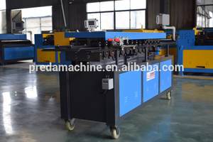

TDF Flange Former T-12
Last updated: October 12, 2026
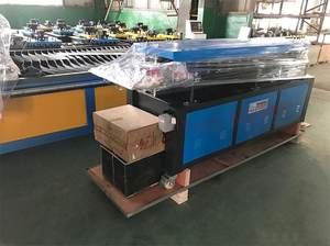
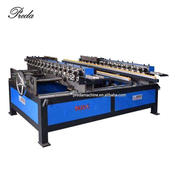
Single-head TDF flange forming machine T-12 for standard rectangular duct flange production.
Technical Specifications
What is a TDF Flange Former T-12?
A flange forming machine is sheet metal equipment that produces TDF (Transverse Duct Flange) or TDC (Transverse Duct Connector) flanges on the edges of rectangular duct panels. These flanges allow duct sections to be bolted together with gaskets for air-tight connections. Flange formers are typically used in conjunction with auto duct lines or as standalone machines for custom ductwork fabrication.
Key Features
- Standard TDF profile
- Easy setup and operation
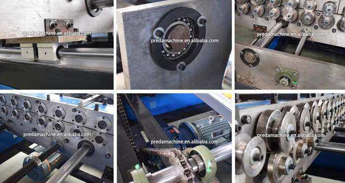
- Hardened forming rollers
- Reliable continuous duty
Still Losing Money to Slow Flange Installation and Poor Seals?
Every HVAC duct shop faces the same bottleneck: manual flange forming and riveting. When your team spends hours on inconsistent flange dimensions, your production capacity drops, labor costs rise, and deadlines slip. The TDF Flange Former T-12 is engineered to eliminate these inefficiencies — automating TDF flange former T-12 while delivering consistent, factory-grade quality.
In this guide, we break down exactly how this machine transforms your single head TDF machine workflow, what specifications matter for your operation, and how to calculate your return on investment. Whether you run a 3-person job shop or a 50-employee production facility, understanding these details directly impacts your bottom line.
How It Transforms Your Production Line
The TDF Flange Former T-12 operates on a proven principle: TDF flange former T-12 should be a continuous, automated process — not a series of manual interventions. Here is the step-by-step workflow that makes this possible:
Panel Feeding
The duct panel edge is fed into the flange forming rollers, with adjustable guides ensuring proper alignment.
Flange Roll Forming
Multiple roller stations progressively form the TDF/TDC flange profile — creating the integral flange that replaces traditional angle iron frames.
Corner Notching (Optional)
Integrated notching stations cut the corner reliefs needed for clean 90° flange corners.
Corner Crimping
Hydraulic or pneumatic corner tools crimp the flange corners, creating a rigid, square connection point.
Technical Specifications & Performance Data
Every specification on this machine is chosen for a reason. The table below shows not just the numbers, but what each one means for your daily production:
| Parameter | This Machine | What It Means for You |
|---|---|---|
| Control System | PLC with touchscreen | Easy programming, consistent results, minimal training |
| Construction | Heavy-duty steel frame | Vibration-free operation, 10+ year service life |
| Certification | CE certified | Meets European safety and quality standards |
| Warranty | 2 years | Peace of mind with comprehensive factory warranty |
Problems Solved: Before vs. After
We asked 50+ HVAC fabricators about their biggest production headaches. Here is how this machine directly addresses each one:
| Without This Machine | With This Machine |
|---|---|
|
✕ Angle iron flanges are heavy and slow
Welding angle iron takes 10-15 min per duct, adds weight |
✓ TDF integral flange formed in seconds
Flange time reduced to 30 seconds, 40% lighter |
|
✕ Flanges don't align on site
Gaps between flanges cause air leakage, need shimming |
✓ CNC-formed flanges with ±0.3mm accuracy
Perfect flange alignment, gasket seals every time |
|
✕ Riveting is slow and labor-intensive
Each flange needs 8-12 rivets, 5-10 minutes per duct |
✓ TDF flange is integral — no rivets needed
Eliminate riveting entirely, save 70% assembly time |
|
✕ Corner gaps and leaks
Poor corner construction is the #1 leak source |
✓ Hydraulic corner crimping creates tight corners
Leakage class C compliance, no corner leaks |
Where It Fits in Your Factory
This machine is versatile enough to serve multiple production scenarios. Here are the most common configurations our customers use:
Commercial HVAC Ductwork
TDF flanges are the global standard for commercial rectangular duct connections — used in offices, hospitals, schools, and retail.
Industrial Ventilation
TDC flanges for high-pressure industrial systems where heavier gauge and stronger connections are required.
Duct Retrofit & Replacement
Upgrading old angle-iron duct systems to modern TDF flange technology for better sealing and faster installation.
Prefabrication Facilities
High-volume duct prefab shops where consistent flange quality is essential for just-in-time delivery to construction sites.
Frequently Asked Questions
Click each question to see the answer. These are the questions our sales engineers hear most often:
T-12 Compared With the Other Flange Formers We Build
The T-12 is the entry point into TDF flange forming: one forming head, one edge per pass. It is the right machine when your duct panels are standard commercial sizes and you are replacing hand-applied angle iron. The table below is the decision matrix our sales engineers actually use when a customer cannot decide between the T-12, the T-16, and a duplex head.
| Model | Forming method | Practical gauge range | Choose it when |
|---|---|---|---|
TDF Flange Former T-12 This machine — single head, one edge per pass | 0.5–1.2 mm (24–18 ga) Forms one flange edge per pass; panel is turned for the second edge | Up to 1.2 m panel width, 26–20 ga Standard commercial HVAC, moderate volume | You flange up to roughly 400 panels a day and want the lowest capital cost Panel handling is manual; two passes per panel |
Heavier frame and drive, same single-head principle | 0.5–1.5 mm (24–16 ga) Deeper roll set and higher torque head | Up to 1.6 m panel width, 24–18 ga Larger ducts and heavier gauge | You run 18 ga or panel widths beyond 1.2 m About 15–20% above the T-12 in price |
Two heads, both edges in one pass | 0.5–1.5 mm (24–16 ga) Both panel edges formed simultaneously | High-volume rectangular duct No panel turning | Flange output is your bottleneck and you exceed ~800 panels a day Roughly doubles throughput per operator |
Forms the TDC profile instead of TDF | 0.5–1.5 mm (24–16 ga) Accepts the separate TDC connector piece | High-static and industrial systems Above 4 in. w.g. | Your specifications call for TDC rather than TDF Not a substitute — the profiles are not interchangeable |
Flange plus integrated cleat notching | 0.5–1.5 mm (24–16 ga) Two operations in one handling | Shops that want corners prepared inline Fewer separate stations | You want to drop the separate corner-notching step Higher capital cost, fewer operators |
Commissioning the T-12: What to Do in the First Week
A flange former that leaves our factory levelled and run-in will still produce scrap on day one if the roll gap is set by eye. These are the steps we walk customers through during installation, in the order that actually matters.
- 1. Bolt the frame to the floor and level it to 0.05 mm/m in both directions. A frame that is out of level feeds the panel at a slight angle, which shows up as a flange that is tall at one end and short at the other.
- 2. Start at material thickness plus 0.05 mm and form a test piece. Increase in 0.02 mm steps until the flange holds its height after springback.
- 3. Push a 1 m panel through without power and measure the flange height at both ends. Any difference above 0.3 mm over 1 m means the fence needs shimming.
- 4. Rolls and the stripper plate settle during the first hour. Dimensions drift in the first 20 pieces and then stabilise.
- 5. Write the roll gap, guide position and speed for 24, 22 and 20 ga on a card fixed to the machine. This single habit removes most of the set-up scrap that new operators create.
- 6. Take a formed panel and dry-fit a corner insert before running the job. Flange height that is 1 mm out will not accept the corner piece.
- 7. Record the setting procedure on video. Shops that keep the knowledge with one person lose it the day that person leaves.
- 8. You need a baseline before you can judge whether a process change helped.
T-12 Faults: Symptom, Cause, Fix
Almost every "the machine is broken" call on a single-head flange former traces back to one of five causes, and four of them are settings rather than parts. Work through this table before you ask for a service visit.
| Symptom | Most likely cause | What to do |
|---|---|---|
Flange height varies along the panel Guide fence not square to the roll axis | The panel is entering at a slight angle, so one end is formed deeper Shows as a wedge-shaped flange | Square the fence to the rolls with a 1 m square, then re-check with a test panel Re-tighten the fence bolts after adjustment |
Flange springs back open after forming Roll gap too large for the gauge | Insufficient plastic deformation, so the material recovers Worse on 20 ga and on stainless | Reduce the roll gap in 0.02 mm steps until the flange holds height Do not compensate by slowing the machine |
Material marks or scoring on the flange face Roll surface damaged or a chip stuck in the pass | A sliver of galvanising or a burr from a sheared edge is being rolled into the surface Usually appears after cutting blanks on a worn shear | Clean the rolls with a brass brush, never steel, and deburr blanks before forming Inspect the roll surface under a bright light |
Panel stalls or slips mid-pass Roll gap too tight, or drive belt tension low | The head is overloading on heavy gauge, or the belt is slipping under load Common after a gauge change with no setting change | Open the gap to the recorded value for that gauge and check belt tension If the motor current stays high, call us — do not keep running |
Corner pieces will not seat Flange height outside tolerance | Typically 0.5–1 mm out, often from forming a different gauge on the previous job The corner die is less forgiving than the flange itself | Re-set to the recorded value for the current gauge and re-form a test panel Keep one gauge per batch until the operator is experienced |
Oil weeping from the gearbox Breather blocked or over-filled | Pressure builds in the gearbox and pushes oil past the seal Often mistaken for a failed seal | Clean the breather and check the level with the machine level and stopped Only replace the seal if weeping continues for a week after that |
Professional Packaging & Global Shipping
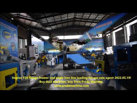
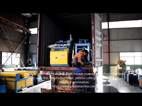
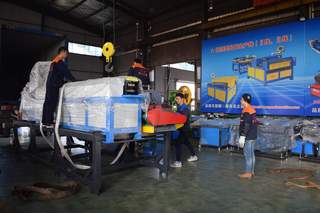
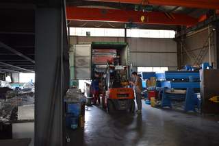
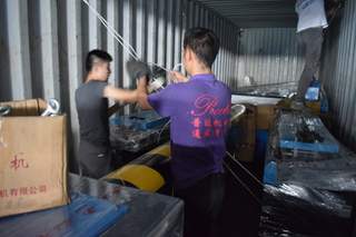
Every machine is professionally packaged and secured in a container for safe delivery to your port. We send you loading photos before the ship sails.
Calculate Your Return on Investment
Based on average industry data, here is what a typical customer saves after installing this machine:
* Figures based on average customer data for a shop producing 300-800 duct sections per month. Your actual results will vary based on production volume, labor rates, and current efficiency levels. Contact our engineers for a customized ROI calculation based on your specific operation.
Ready to Upgrade Your TDF Production?
Get a customized quote within 24 hours. Our engineers will help you configure the right machine for your specific production requirements.
WhatsApp / WeChat: +86-18355321923 | Email: jason@predamachine.com
Related Products

Buying Guides for This Machine Type
Before you request a quote: how this machine class compares, what it costs, and how to size it for your production volume.
TDF vs TDC Flange Guide
The two dominant rectangular duct flange systems compared on sealing, speed and installed cost.
Read the guide → Buying GuideTDF Corner Making Guide 2026
Corner machine vs corner matics vs hand molds: the real cost per corner at different volumes.
Read the guide → Buying GuideTDF Flange Former Buying Guide 2026
T-12 vs T-16 vs Duplex vs Dual Head — throughput, gauge range and shop-size fit.
Read the guide → ComparisonTDF Bender: Electric vs Pneumatic
Power source choice for TDF benders — air supply requirements, cycle speed and maintenance load.
Read the guide →