When a shop orders an automatic duct line, the model and its gauge range usually get most of the attention, yet the arrangement on the floor decides whether the line actually keeps producing. A straight-through arrangement runs coil in one end and blanks out the other along a single axis. A U-shape or compact arrangement turns the material flow back so the feed and the exit sit closer together, which fits a narrower workshop but changes how panels reach the lockformer, flange former and seam locker downstream. This guide compares the two layouts by floor footprint, material path, operator reach and downstream access, and pairs the comparison with the AML-3 and AML-6 line specifications so the layout decision follows the actual workshop rather than a brochure diagram.
Why the Physical Arrangement Outlasts the Model Choice
Machine parameters such as thickness band, maximum width and working speed stay fixed once the line runs, but the floor plan around the line keeps changing as the shop adds equipment, shifts section types or takes on new contracts. A line that was easy to feed when the hall was empty can become a bottleneck once a flange former, a seam locker or a coil rack moves close to the feed end. The arrangement chosen at installation determines whether those additions can still be reached, whether the coil car can swing its second coil without hitting a column, and whether an operator walking a panel to the next station crosses the main material path.
Layout also affects downstream quality. A blank that exits the line on the wrong side must be carried across the machine or turned around before it reaches the lockformer. That carry adds handling time, increases the chance of a dinged edge on a sensitive galvanized surface, and makes blank squareness harder to preserve between the line and the forming station. Matching the line's exit side to the existing downstream bench is one of the least expensive quality decisions a shop can make, because it depends on arrangement rather than on extra machine capacity.
Straight-Through Layout: Coil In, Blank Out Along One Axis
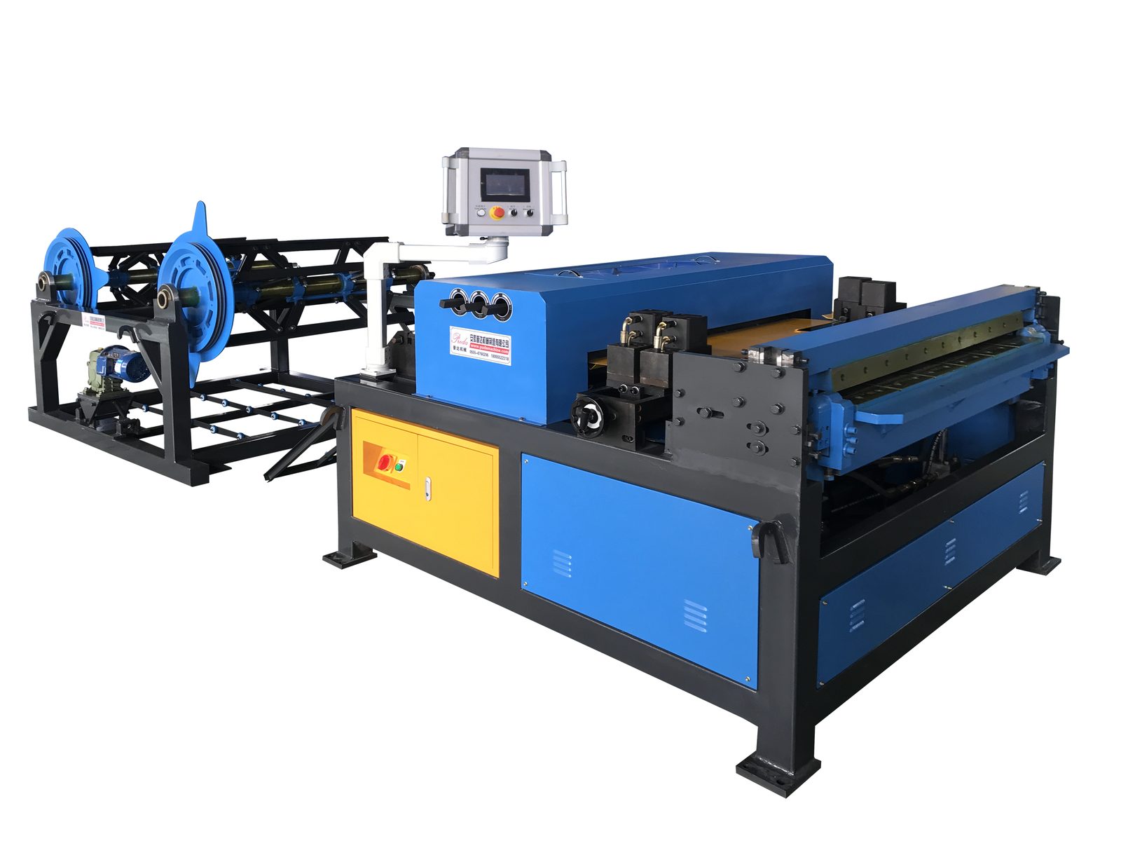
A straight-through auto duct line places the coil car, leveling, grooving/notching and shearing stations in a single line, with the strip moving in one direction from feed to exit. The feed end accepts the coil and the exit end releases the finished blank onto a table or conveyor that leads to the next station. This arrangement keeps the material path open and predictable: a panel follows the same direction through the whole line, and an operator working the run can watch the feed and the exit from one side without crossing between them.
The straight layout suits a workshop with a long clear wall, a dedicated rectangular-duct bay, or a shop that intends to add more stations in a line later. It also leaves room along the machine side for maintenance access to rollers, blades and the control panel. Its main demand is length: the line needs a floor run long enough for the coil car swing, the body of the line and the exit table, plus an aisle at both ends for coil delivery and panel removal. Where the hall is narrow or shared with other equipment, that length is the constraint that pushes a shop toward a U-shape.
U-Shape and Compact Arrangements
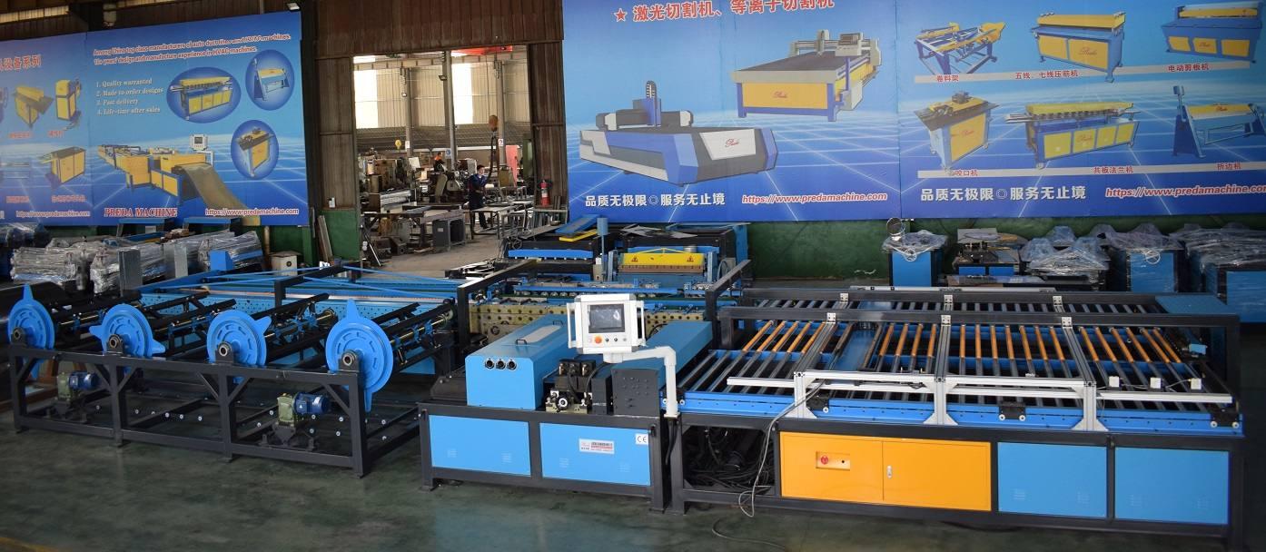
A U-shape arrangement folds the flow so the line returns along itself, bringing the feed end and the exit end closer together. The body of the line still runs its stations in sequence, but the overall floorprint occupies depth rather than a long single run. This is the common solution for a narrower workshop, a line that shares a hall with spiral machines or a brake bay, or a shop where the rectangular output is one activity among several on the same floor. The panel still passes each station in order; the difference is the direction in which the sequence turns on the floor.
The trade-off sits in material handling and access. A folded flow shortens the walk between feed and exit, but it can place the coil car and the exit bench near each other, so the second coil swing and the removed panel need clear separation to avoid crowding. Maintenance reach on the inner side of the U also needs checking before installation, because rollers and blades on the return leg can sit close to the frame. For a shop that cannot spare a long wall, the U-shape recovers floor area that a straight line would require, provided the inner access and coil swing are planned rather than discovered after delivery.
How the Two Layouts Compare on the Floor
The comparison below frames each arrangement by how work moves, where people walk, and which floor conditions drive the choice. The rows describe the physical workflow rather than machine performance; a line performs the same regardless of whether it stands straight or folded.
| Dimension | Straight-through line | U-shape / compact line |
|---|---|---|
| Material path | Coil in one end, blank out the other along a single axis | Flow folds back so feed and exit sit close together |
| Floor demand | Needs a long clear run for coil car, line body and exit table | Uses depth rather than a long single run, suits narrow halls |
| Operator walk | Feed and exit reachable from one side, no crossing between | Feed and exit close, but inner return leg needs planned reach |
| Downstream reach | Exit side aligns along the line's length to the next bench | Exit faces back toward the feed side; match bench to that side |
| Coil car swing | Open aisle at the feed end for the two-station coil car | Check clearance between second coil and exit bench |
| Maintenance aisle | Open side along the straight body for rollers and blades | Inner leg access must be checked before installation |
| Best fit | Dedicated rectangular bay, long wall, future line extensions | Shared hall, narrow workshop, mixed-machine floor |
Reading the Line Specifications the Layout Depends On
The arrangement decision sits on top of the machine's specification band. Two Preda line families are compared below, using the figures listed on the product pages. Both cover the same thickness band and width configurations; the difference in working speed maps onto how much steady weekly rectangular output the shop expects, while the width configuration is chosen against the widest panel on the tender list.
| Specification | AML-3 Auto Duct Line | AML-6 Auto Duct Line |
|---|---|---|
| Models | AML-3-1300 / 1500 / 1600 | AML-6-1300 / 1500 / 1600 |
| Material thickness | 0.45-1.5 mm | 0.45-1.5 mm |
| Maximum width | 1300 / 1500 / 1600 mm | 1300 / 1500 / 1600 mm |
| Working speed | 12 m/min | 16 m/min |
| Material handling | Two-station coil car queues the next coil | Two-station coil car queues the next coil |
| Position in the lineup | Balanced line for steady rectangular production | Higher-speed line for heavier weekly output |
None of these figures changes between a straight and a U-shape build; the layout governs how the line's output reaches the next station and how the coil gets in. Width configuration and speed are chosen from orders, while arrangement is chosen from the floor plan. Order the configuration against your widest panel and largest steady output, then tell the supplier which wall and which downstream bench the line must align with, so the factory can quote the arrangement that matches that layout.
Planning the Floor Plan Before You Order
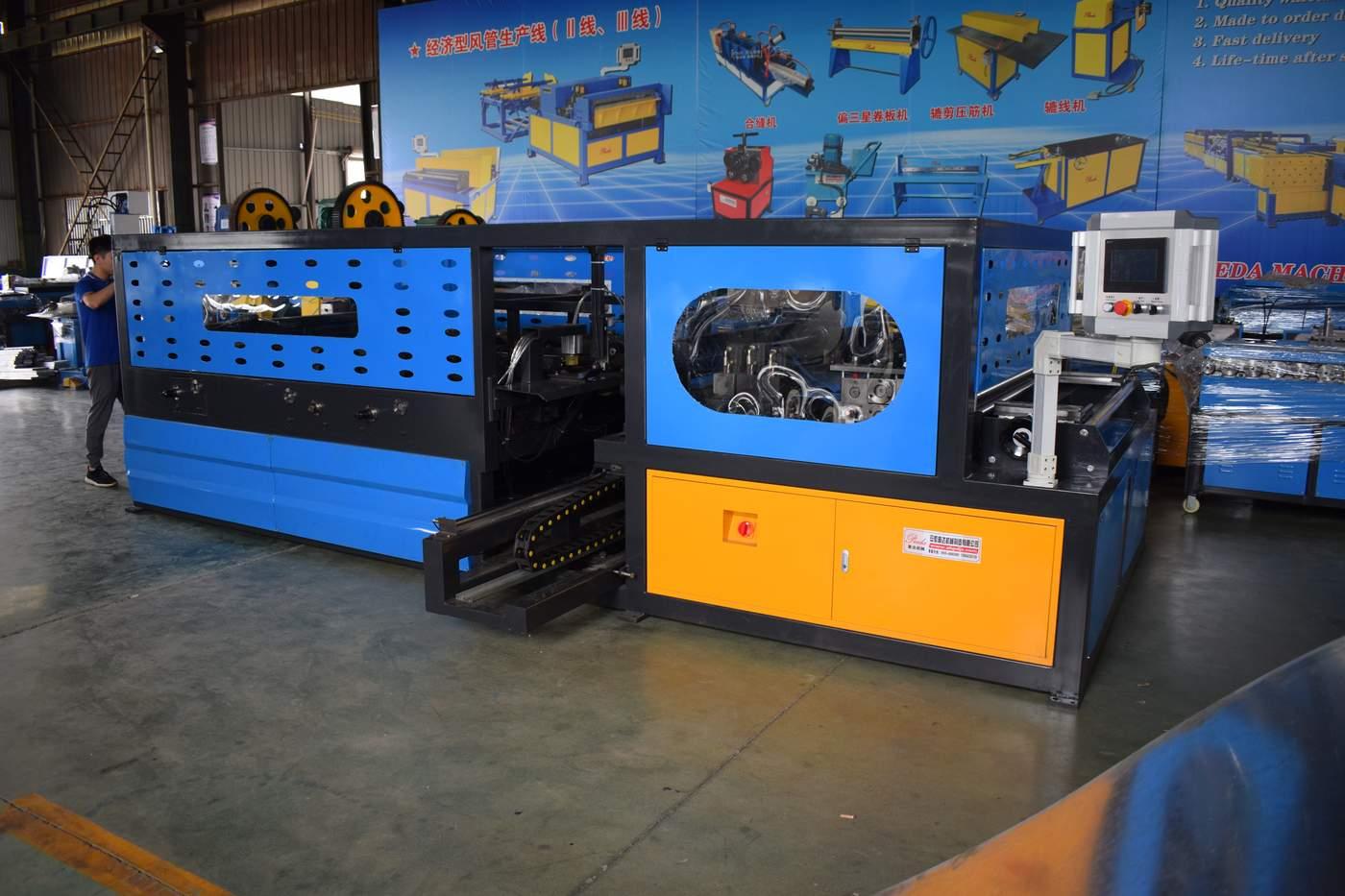
A layout decision made on the machine's own dimensions usually misses the surrounding aisles and stations. Measure the hall before matching a line to it, and let those measurements drive straight versus U-shape rather than the other way around.
- Measure the longest clear wall run. If a dedicated bay can take the coil car, line body and exit table in one direction, a straight layout is usually the simpler path; if the available depth exceeds the available length, a U-shape is worth quoting.
- Map the feed path for coil delivery. The two-station coil car needs a place to hold the second coil without blocking the aisle or the inner leg of a folded line.
- Place downstream benches against the exit side. Identify where the lockformer, flange former and seam locker stand today, and choose the arrangement that lets the blank reach them without crossing the main path.
- Keep a maintenance aisle. Rollers, blades and the control panel need reach along the body; on a U-shape, confirm the inner leg has enough room to service.
- Leave expansion space. If the shop expects a second line or an added flange station, a straight line extends along its own axis more easily than a folded arrangement does.
Common Layout Mistakes That Cut Output
- Choosing the arrangement from the brochure photo only. A line photographed in a long showroom bay may not fit the workshop's actual wall length.
- Forgetting the exit-side bench. A blank that must be turned or carried across the machine loses the sequence advantage the line was bought for.
- Crowding the coil car. A second coil swing blocked by a column or bench stops the run for a manual swap.
- Leaving no inner-leg aisle on a U-shape. Maintenance reach that exists on paper but not on the floor turns into downtime when a roller needs changing.
- Planning layout before configuration. Width and speed are set by orders; layout follows the floor. Swapping the order of these decisions buys the wrong line on either arrangement.
What a Line Layout Cannot Change
A good arrangement removes cross-shop carries and keeps the blank square between stations, but it does not fix an undersized width configuration, an outdated lockformer downstream or a section mix that changes size on every job. The blank that leaves a well-placed line still reaches the seam locker and flange former in good condition; the quality of the final section still depends on those stations' setup, roller condition and first-section checks. Layout is the first layer of consistency, not the whole quality system.
It also does not replace trained operators. Whether the line stands straight or folded, the setter still reads the drawing, recalls the section program, measures the first blank and watches the run for size or notch mismatch. A tidy floor plan makes that work easier; it does not remove the need for the knowledge behind it.
Sketch the feed, the body and the exit before quoting
On a floor sketch, mark the coil delivery aisle, the line body, the exit table and the existing downstream bench. If the line's exit can face that bench on its own axis, the straight layout usually works; if the bench sits on the same side as the feed, the folded flow is the arrangement to ask about. Send that sketch with the configuration request so the supplier prices the matching layout.
Preda Care Service Promise
Every Preda Machine ships CE certified with a two-year warranty, backed by 24/7 technical support, free spare parts shipping, remote PLC programming assistance and a global agent network. A support engineer can review your hall measurements, downstream bench positions and section widths against the AML-3 and AML-6 configurations, and advise whether a straight or U-shape arrangement fits the floor.
Match the Line Layout to Your Floor Plan
Share the hall dimensions, the downstream stations you already run and the widest sections your projects call for, and we will map them to a straight-through or U-shape arrangement with the right AML-3 or AML-6 configuration.
Compare Auto Duct Lines →Frequently Asked Questions
Does a U-shape line produce slower than a straight-through line?
No. The working speed and station sequence are the same in either arrangement; the U-shape only folds the material flow on the floor. What changes is floor footprint, walk distance and access, not the metres per minute through the line.
Which layout fits a narrow shared workshop?
A U-shape or compact arrangement usually fits a narrow hall better, because it uses floor depth rather than a long single run. Confirm the inner-leg maintenance reach and the coil car swing before committing to the folded flow.
How do I choose between 1300, 1500 and 1600 mm width?
Choose the configuration against the widest panel your projects specify, not the average section. Both the AML-3 and AML-6 are offered in 1300, 1500 and 1600 mm, with 0.45-1.5 mm material band; speed is then set by weekly output, 12 m/min on the AML-3 and 16 m/min on the AML-6.
Should the lockformer and flange former sit next to the line?
They should receive the blank on the line's exit side without a cross-shop carry. On a straight line that aligns along the body; on a U-shape it faces the feed side, so position those benches to match that direction.