This guide covers everything you need to know about Round Duct Fittings. Key takeaways: detailed specifications, cost comparisons, pros and cons, maintenance requirements, and expert recommendations from Preda Machine — a leading HVAC duct machinery manufacturer since 2008, serving 60+ countries.
In This Guide
Types of Round Duct Fittings
| Fitting Type | Function | Pressure Loss (C) | Fabrication Difficulty |
|---|---|---|---|
| 90° Elbow (gored) | Change direction 90° | 0.25-0.45 | Medium |
| 45° Elbow | Change direction 45° | 0.12-0.20 | Medium |
| Tee (straight) | Split airflow straight | 0.15-0.30 | Medium |
| Tee (branch) | Split airflow to branch | 0.30-0.60 | High |
| Reducer (concentric) | Change duct size | 0.05-0.15 | Low |
| Reducer (eccentric) | Change size offset | 0.08-0.20 | Medium |
| Takeoff (saddle) | Branch from main duct | 0.20-0.50 | High |
| End cap | Seal duct end | N/A | Low |
| Cross | 4-way connection | 0.30-0.70 | High |
Elbows and Bends
Round duct elbows are typically fabricated using the gore method — cutting wedge-shaped gores from flat sheet and rolling them into curved sections. The number of gores determines the smoothness of the bend:
🎬 Watch Related Product Videos
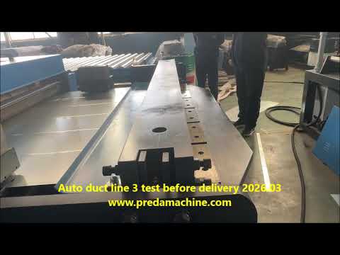
See our machines running in real factory tests


| Elbow Type | Gores per 90° | Radius (× diameter) | Pressure Loss (C) |
|---|---|---|---|
| Short radius | 3 gores | 1.0D | 0.45 |
| Medium radius | 5 gores | 1.5D | 0.30 |
| Long radius | 7 gores | 2.0D | 0.20 |
| Smooth bend | 9+ gores | 2.5D+ | 0.15 |
A gorelocker machine (also called an elbow machine) automates the process of cutting and forming gores, reducing fabrication time from 30 minutes per elbow to 3-5 minutes. Preda Machine offers both electric and hydraulic gorelocker models for duct diameters 80-1600mm.
Best Practice
Use 5-gore elbows with 1.5D radius as the standard for commercial HVAC. They balance pressure loss (C=0.30) with fabrication cost. Short-radius 3-gore elbows should only be used in tight spaces where a longer radius won't fit.
Tees and Takeoffs
Straight Tee
A straight tee has the branch entering the main duct at 90°, with a smooth internal transition. The straight-through path has low pressure loss (C=0.15), while the branch path has higher loss (C=0.30-0.60) due to the 90° turn.
Wye Tee (45° Branch)
A wye has the branch entering at 45° instead of 90°, significantly reducing branch pressure loss (C=0.20-0.35). Wyes are preferred for balanced systems but require more space and are more expensive to fabricate.
Saddle Takeoff
A saddle takeoff is a branch connection that wraps around the main duct like a saddle. It is cut into the main duct on site and attached with screws and sealant. Saddle takeoffs are flexible but have higher pressure loss and leakage potential.
Reducers and Transitions
| Reducer Type | Length (× diameter) | Pressure Loss (C) | Application |
|---|---|---|---|
| Concentric (short) | 1.5D | 0.15 | Space-limited |
| Concentric (standard) | 3.0D | 0.08 | Standard |
| Concentric (long) | 5.0D | 0.05 | Low noise |
| Eccentric (flat) | 3.0D | 0.10 | Ceiling installation |
Concentric reducers have the centerline aligned, making them ideal for vertical ducts and symmetrical layouts. Eccentric reducers have one flat side, used when the duct must run flush with a ceiling or floor. Always use a reducer length of at least 3× the diameter difference for minimum pressure loss.
Pressure Loss Coefficients Reference
| Fitting | Coefficient (C) | Equivalent Duct Length |
|---|---|---|
| 90° elbow (5-gore, 1.5D) | 0.30 | 15 ft (4.5m) |
| 45° elbow | 0.15 | 7 ft (2.1m) |
| Tee (branch flow) | 0.45 | 22 ft (6.7m) |
| Tee (straight flow) | 0.15 | 7 ft (2.1m) |
| Wye (branch) | 0.25 | 12 ft (3.7m) |
| Concentric reducer | 0.08 | 4 ft (1.2m) |
| Saddle takeoff | 0.40 | 20 ft (6.1m) |
| Round-to-rectangular transition | 0.20 | 10 ft (3.0m) |
Total system pressure loss = sum of all fitting losses + straight duct friction loss. Fittings typically account for 50-70% of total pressure loss in a well-designed duct system.
Fabrication Equipment
| Equipment | Produces | Capacity | Price Range |
|---|---|---|---|
| Electric gorelocker | Elbows, gores | 80-800mm | $3,000-$6,000 |
| Hydraulic gorelocker | Elbows, gores (heavy) | 200-1600mm | $6,000-$12,000 |
| Plasma cutter | Custom fittings, patterns | Any shape | $5,000-$15,000 |
| Slip roll | Round bodies, reducers | 1.5mm × 1300mm | $1,000-$3,000 |
| Spot welder | Assembly | 1.5mm | $800-$2,000 |
For a complete round duct fitting shop, the essential equipment is: spiral duct machine + gorelocker + plasma cutter + slip roll + spot welder. This combination produces all standard round duct and fittings with minimal manual labor.
Frequently Asked Questions
Preda Care: After-Sales That Never Expires
When you invest in HVAC duct manufacturing equipment, downtime costs money. With Preda Care, you get lifetime technical support — not just during warranty, but for the entire life of your machine. Our global agent network provides local service in 40+ countries.
- 24-hour response time
- Free spare parts shipping
- Remote PLC program support
- Global agent network
- Video call troubleshooting
- On-site installation
Elbow Fabrication: Segments, Radius and Pressure Loss
Elbows are the highest-loss fitting in most round systems and the most common source of noise. Three variables control the loss: centre-line radius ratio, number of segments, and whether turning vanes are fitted.
| Elbow type | Radius ratio (R/D) | Loss coefficient | When to use |
|---|---|---|---|
| Short-radius segmented | 1.0 | 0.35 – 0.50 | Tight spaces, low velocity |
| Standard segmented | 1.5 | 0.20 – 0.30 | General supply and return |
| Long-radius segmented | 2.0 | 0.15 – 0.22 | High velocity, noise-sensitive |
| Segmented with turning vanes | 1.0 | 0.10 – 0.15 | Where space is tight but loss must be low |
| Smooth radius (gorelocker, 7+ gores) | 1.5 | 0.18 – 0.25 | Exposed architectural runs |
| Mitre with vanes | 0.5 | 0.20 – 0.30 | Plant room plenums |
Increasing the radius ratio from 1.0 to 1.5 typically halves the loss. On a main run with four elbows at 12 m/s, that is worth roughly 40–60 Pa of static pressure — a meaningful difference in fan power over the life of the building.
Take-offs and Branch Connections
Branch connections are where most systems lose balance. The geometry of the entry into the main duct determines both the loss and how much air the branch actually draws.
| Fitting | Loss coefficient (branch) | Balance behaviour | Best application |
|---|---|---|---|
| 45° saddle tap | 0.4 – 0.6 | Predictable | Standard branch take-off |
| 90° saddle tap | 1.0 – 1.4 | Poor, needs damper | Only where space forces it |
| Conical tee | 0.3 – 0.5 | Good, self-balancing | Medium and high pressure |
| Shoe tap | 0.5 – 0.8 | Good | Large branches off a main |
| Flat stamped take-off | 0.8 – 1.2 | Fair | Low cost, low velocity |
| 90° tee (bullhead) | 1.2 – 1.8 | Poor | Avoid on supply; acceptable on low-velocity return |
Angle Matters More Than Fitting Cost
A 45° entry costs the same to fabricate as a 90° entry and roughly halves the branch loss. If your take-off tooling can do 45°, do 45°. The balancing dampers will then have range left to work with instead of being fully open on every branch.
Reducers and Transitions
| Transition | Max recommended included angle | Loss coefficient | Fabrication note |
|---|---|---|---|
| Concentric reducer, round | 30° | 0.05 – 0.10 | Roll on a roller or form on the spiral line |
| Eccentric reducer, round | 30° one side | 0.08 – 0.15 | Keeps the duct bottom level for drainage |
| Round-to-rectangular | 60° total | 0.15 – 0.35 | Must be long enough to avoid separation |
| Rectangular-to-round (plenum) | 90° permitted in a plenum | 0.5 – 1.2 | Use inside a plenum, not in a duct run |
| Square-to-round | 60° total | 0.20 – 0.40 | Common at fan inlet and outlet |
Exceeding the recommended angle causes flow separation: the air does not follow the wall, effective area drops, and the fitting generates noise. If space does not permit the correct length, fit a shorter transition with turning vanes rather than a longer one without.
Need Equipment Recommendations?
Tell us your duct specifications, daily production volume, and workshop size — our engineers recommend the perfect equipment configuration within 24 hours.
Get Free ConsultationContinue Reading: Related Guides
Go deeper on this topic, then compare the machines that do the work.
Gorelocker Elbow Machine Guide 2026
Hydraulic vs electric gorelockers: cycle time, gauge range and which elbow sizes each handles.
Read the guide → ComparisonGorelocker Elbow Making Machine
How hydraulic and electric elbow machines differ in setup, tooling changeover and operator skill.
Read the guide → ComparisonSpiral Tubeformer Buying Guide 2026
Head-to-head comparison of PD1600, PD1200 and PD2000 — capacity, price band and ideal shop size.
Read the guide → ReviewSpiral Tubeformer PD1600 Review & Setup
Setup sequence, operator settings and real customer output data from the PD1600 platform.
Read the guide →Machines covered in this topic
Compare specifications, gauge range and output for the machines discussed above.
Electric Elbow Forming Machine XMWT-A
Electric gorelocker for fast elbow segment forming
View specs → MachineHydraulic Elbow Making Machine
Hydraulic gorelocker for elbow segment production
View specs → MachineHeavy Duty Spiral Tubeformer PD-2000
Φ200–2000 mm heavy-gauge spiral tube production
View specs → MachinePlasma Cut Spiral Tubeformer PD1600-PLASMA
Spiral tubeformer with integrated plasma cutting
View specs →