This guide covers everything you need to know about Duct Leakage Testing. Key takeaways: detailed specifications, cost comparisons, pros and cons, maintenance requirements, and expert recommendations from Preda Machine — a leading HVAC duct machinery manufacturer since 2008, serving 60+ countries.
In This Guide
Why Duct Leakage Matters
Duct leakage is the unintended loss of conditioned air through gaps, holes, and poorly sealed joints in the ductwork system. Studies show that typical commercial duct systems lose 10-25% of supply air through leakage, with some poorly installed systems losing 30% or more.
🎬 Watch Related Product Videos
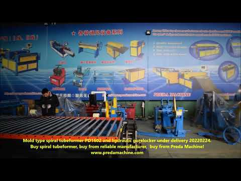
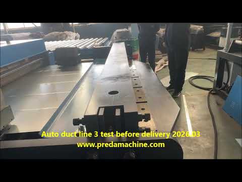
See our machines running in real factory tests

The impacts are significant:
- Energy waste — Leaked air is already heated or cooled, representing pure energy loss
- Comfort complaints — Rooms at the end of leaky runs don't get enough airflow
- Equipment oversizing — Systems are often oversized to compensate for leakage
- Code violations — Most energy codes now require duct leakage testing
- Indoor air quality — Return duct leakage can draw in unconditioned, contaminated air
Cost Impact
For a 50,000 sq ft office building with 15% duct leakage, the annual energy cost is approximately $8,000-$12,000 in wasted heating and cooling. Sealing the ducts to achieve 5% leakage typically pays for itself in 1-2 years.
SMACNA Leakage Classes
SMACNA (Sheet Metal and Air Conditioning Contractors' National Association) defines duct leakage classes based on allowable leakage per 100 sq ft of duct surface area at a given static pressure.
| Class | Allowable Leakage (cfm/100 sq ft @ 1" WG) | Application |
|---|---|---|
| Class A (Sealed) | ≤ 3 cfm | High efficiency, LEED, energy code |
| Class B (Commercial) | ≤ 6 cfm | Standard commercial HVAC |
| Class C (Basic) | ≤ 12 cfm | Industrial, low-pressure |
| Class D (Unsealed) | ≤ 48 cfm | Residential, basic |
Most modern energy codes (IECC, ASHRAE 90.1) require Class A or Class B for commercial ductwork. LEED projects typically require Class A with verified testing.
Test Methods
Method 1: Total Duct Leakage Test
The entire duct system is sealed at all outlets, and a calibrated fan pressurizes the system to a specified test pressure (typically 1" WG for low-pressure systems). The airflow required to maintain the test pressure equals the total leakage.
Method 2: Sectional Leakage Test
Individual duct sections are isolated and tested separately. This method is useful for identifying specific leakage points and is required for some high-pressure systems.
Method 3: Tracer Gas Test
A tracer gas (typically SF6 or CO2) is injected into the duct, and sensors measure gas concentration at suspected leak points. This method is more expensive but can pinpoint exact leak locations.
Test Equipment
| Equipment | Function | Price Range |
|---|---|---|
| Duct leakage tester (minneapolis) | Calibrated fan + pressure gauge | $1,500-$4,000 |
| Anemometer | Measure airflow velocity | $100-$500 |
| Manometer | Measure static pressure | $50-$300 |
| Duct sealing tape | Seal outlets during test | $20-$50 |
| Smoke pencil | Visual leak detection | $10-$30 |
The most common test instrument is the Minneapolis Duct Leakage Tester, which combines a variable-speed fan, pressure sensor, and flow measurement in one portable unit.
Energy Savings Calculation
Use this formula to estimate energy savings from duct sealing:
Annual Savings = (Leakage Reduction CFM × 0.000157 × Hours × ΔT × Cost per BTU)
| System Size | Current Leakage | After Sealing | Annual Savings |
|---|---|---|---|
| 10,000 CFM | 15% (1,500 CFM) | 5% (500 CFM) | $3,000-$5,000 |
| 25,000 CFM | 20% (5,000 CFM) | 5% (1,250 CFM) | $8,000-$12,000 |
| 50,000 CFM | 25% (12,500 CFM) | 5% (2,500 CFM) | $18,000-$28,000 |
How to Reduce Duct Leakage in Fabrication
- Use Pittsburgh lock seams — Properly formed Pittsburgh seams leak less than slip joints. Use a quality lockformer for consistent seams.
- Seal all transverse joints — Apply duct sealant (mastic) to all TDF/TDC joints, especially on the negative-pressure side.
- Use gaskets on flanges — EPDM or neoprene gaskets between flange connections reduce leakage by 50-70%.
- Seal around penetrations — All rod, pipe, and wire penetrations through duct walls must be sealed.
- Inspect before insulation — Test and seal ducts before applying insulation; leaks hidden under insulation are impossible to fix later.
- Use quality equipment — Auto duct lines produce consistent, precise bends and seams that leak less than manually fabricated duct.
Frequently Asked Questions
Preda Care: After-Sales That Never Expires
When you invest in HVAC duct manufacturing equipment, downtime costs money. With Preda Care, you get lifetime technical support — not just during warranty, but for the entire life of your machine. Our global agent network provides local service in 40+ countries.
- 24-hour response time
- Free spare parts shipping
- Remote PLC program support
- Global agent network
- Video call troubleshooting
- On-site installation
Step-by-Step Duct Leakage Test Procedure
This is the field procedure for a duct pressurisation test to SMACNA / ASHRAE methods. Skipping the preparation steps is the usual reason a passing system reports as failing.
- Seal all openings. Every register, grille, damper and open end. Use temporary blanks rated above the test pressure — tape alone will blow off.
- Select test pressure. The greater of the design operating pressure or the code minimum for the duct class. Do not test at 25 Pa if the system runs at 500 Pa.
- Connect the fan and manometer. Measure static pressure at the fan discharge, not at the duct midpoint. Fit a flow meter capable of reading the expected leakage rate.
- Pressurise gradually. Ramp to 50% of test pressure and hold for two minutes. This seats the blanks and reveals gross leaks before you commit to the full test.
- Ramp to full test pressure and hold for five minutes. Record the leakage flow once the reading stabilises.
- Calculate leakage. Compare measured flow against the allowable for the duct class and surface area.
- Locate leaks while still pressurised — listen, use smoke, or feel along seams and joints.
- Repair and re-test. Re-test the whole section, not just the repaired joint.
Measure Surface Area Accurately
Allowable leakage is expressed per square metre of duct surface. Under-measuring the area by 15% makes a failing system look like it passes. Take the area from the fabrication take-off, not from a rough count.
Allowable Leakage by Duct Class
| Class | Pressure range | Sealing standard | Allowable leakage (L/s per m² at 250 Pa) | Typical application |
|---|---|---|---|---|
| Class A / ½ | Up to 250 Pa | Seams only | 0.9 | Low-pressure residential |
| Class B / 1 | 250 – 500 Pa | Seams and joints | 0.45 | Standard commercial supply |
| Class C / 2 | 500 – 750 Pa | Seams, joints, penetrations | 0.25 | Medium-pressure commercial |
| Class D / 3 | 750 – 1000 Pa | All sealed, no exposed fasteners | 0.15 | High-pressure, hospital |
| Class E / 4 | Above 1000 Pa | Fully welded or gasketed | 0.08 | Industrial, laboratory exhaust |
Leakage scales with pressure to roughly the 0.65 power, so results taken at one pressure can be converted: Q2 = Q1 × (P2/P1)0.65. Testing at 250 Pa on a system designed for 750 Pa understates the real leakage by about half.
Where Leaks Actually Come From
Field data from duct leakage repairs, ranked by frequency. Almost all of it is preventable in the shop rather than on site.
| Rank | Leak location | Share of total leakage | Shop-side prevention |
|---|---|---|---|
| 1 | Transverse joint / flange corners | 35 – 45% | Correct corner insert, sealant in the corner before assembly |
| 2 | Longitudinal seam on rectangular duct | 20 – 30% | Properly closed Pittsburgh lock, not hammered |
| 3 | Access door and damper frames | 10 – 15% | Gasket fitted in the shop, not on site |
| 4 | Hanger and support penetrations | 5 – 10% | Avoid self-tappers through the duct wall |
| 5 | Branch take-off connections | 5 – 8% | Proper take-off fitting rather than a cut hole |
| 6 | Spiral tube seam | Under 3% | Correct seam roll gap |
The Corner Is Everything
On rectangular duct with TDF or TDC flanges, the corner is where four pieces meet and where sealant is most often skipped. Fit the corner insert, apply sealant to the mating faces, and pressure-test a sample section in the shop. Finding a corner problem at the bench costs minutes; finding it after handover costs a ceiling.
Need Equipment Recommendations?
Tell us your duct specifications, daily production volume, and workshop size — our engineers recommend the perfect equipment configuration within 24 hours.
Get Free ConsultationContinue Reading: Related Guides
Go deeper on this topic, then compare the machines that do the work.
Spiral vs Rectangular Duct
Which profile wins on material cost, pressure drop and installation labour — with decision rules.
Read the guide → Buying GuideGorelocker Elbow Machine Guide 2026
Hydraulic vs electric gorelockers: cycle time, gauge range and which elbow sizes each handles.
Read the guide → ReviewSpiral Tubeformer PD1600 Review & Setup
Setup sequence, operator settings and real customer output data from the PD1600 platform.
Read the guide → ProcessOval Duct Manufacturing Guide
How flat oval duct is formed from round spiral tube, and when oval beats rectangular.
Read the guide →Machines covered in this topic
Compare specifications, gauge range and output for the machines discussed above.
CNC Rotary Beading Machine RBM-1600-CNC
CNC controlled rotary beading for round duct
View specs → MachineElectric Elbow Forming Machine XMWT-A
Electric gorelocker for fast elbow segment forming
View specs → MachineHydraulic Elbow Making Machine
Hydraulic gorelocker for elbow segment production
View specs → MachinePlasma Cut Spiral Tubeformer PD1600-PLASMA
Spiral tubeformer with integrated plasma cutting
View specs →