An automatic duct line is often described as one machine, but it is a sequence of stations that turns a coil into a ready blank: feed and hold the coil, level the strip flat, form the beads or grooves, notch the corners, shear to size, and pass the panel along to the lockforming, flanging and seam-closing stations downstream. Understanding that sequence explains where blank squareness comes from, which operator checks belong to each step, and how the listed thickness, width and speed figures map onto the stations themselves. This guide walks through the AML-3 and AML-6 line process flow station by station, and sets out what each step contributes and where human judgment still enters.
The Overall Sequence: Coil in, Blank Out
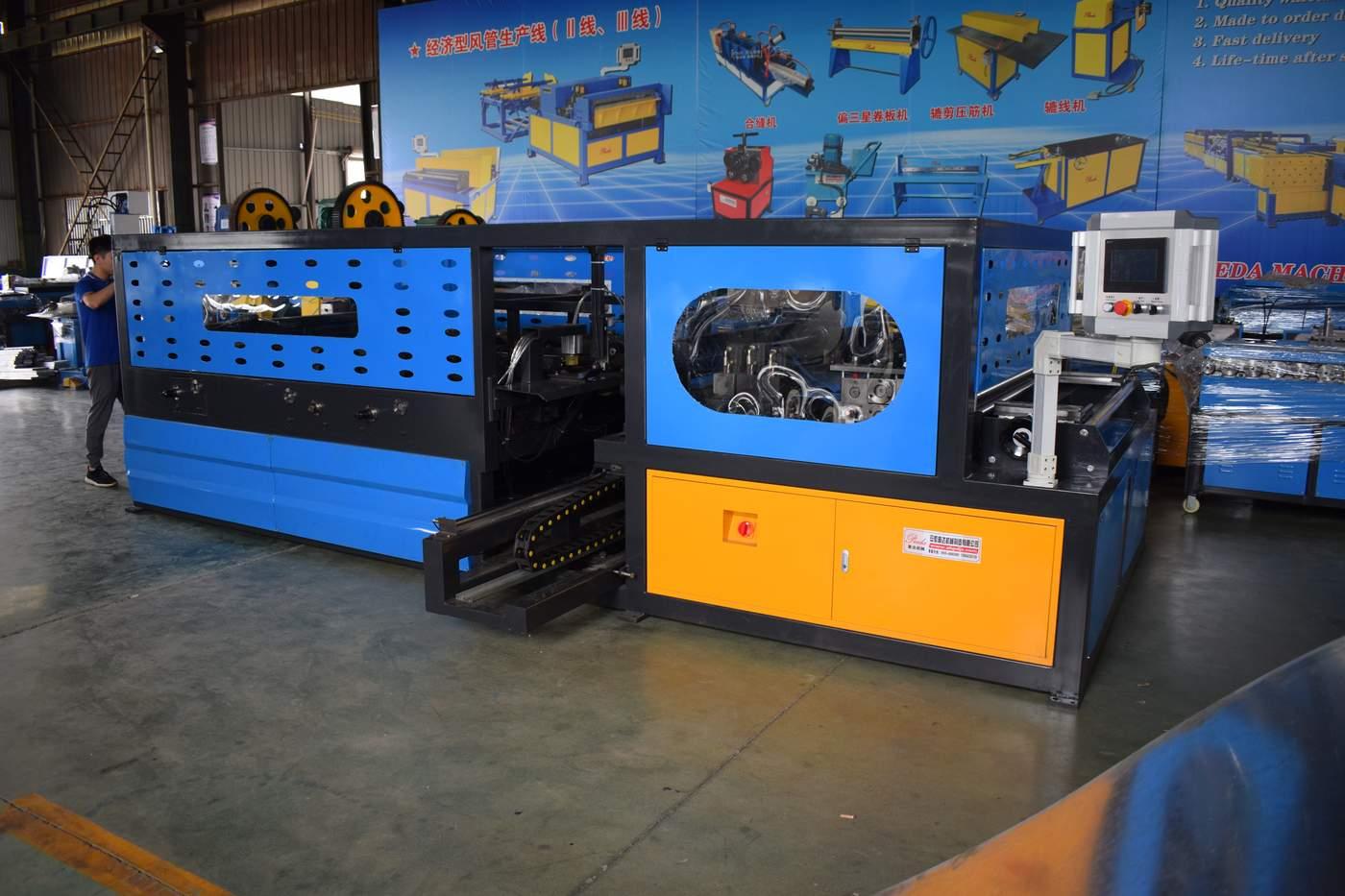
In a coil-fed rectangular duct line, the strip does not wait on separate benches between stages. It travels through the stations in order under the line's feed drive, so a blank reaches the downstream forming stations square and consistently sized. The upstream stations prepare the panel; the line does not close the Pittsburgh seam or form the flange itself - those follow on the lockformer and flange former the shop runs after the blank exits. Reading the line this way keeps expectations clear: the automatic stage is the preparation and feed side of rectangular production, while seam and flange quality still depend on the machines it feeds.
The order of the stations matters because each one corrects or sets a condition the next relies on. A coil that is not leveled reaches the notch and shear with curl; a strip not notched to the section corners cannot fold cleanly; a blank not squared at the shear carries that mismatch into every downstream bend. The process flow below follows the strip through those dependencies rather than treating the stations as independent accessories.
Station 1: Coil Car and Coil Feeding
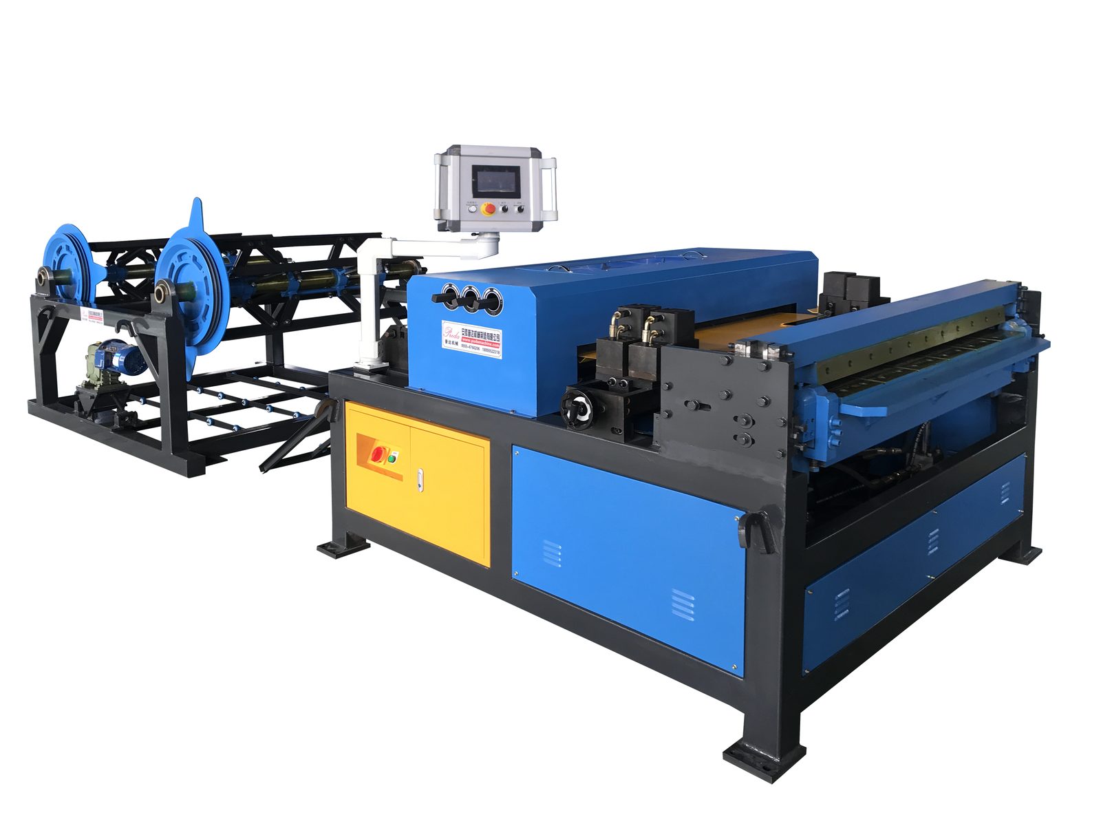
The coil car holds the incoming coil and presents its leading edge to the line's feed. A two-station coil car queues a second coil beside the first, so the run does not stop for a full coil swap: when the active coil empties, the next one is already positioned to lead in. This station's contribution is continuity - keeping strip available without a manual lift and re-thread between coils. Its setup point is coil width and centre alignment; a coil mounted off centre feeds a strip that runs to one side through the later stations.
Operator checks at the feed stage cover coil condition, edge straightness and that the leading edge threads cleanly into the leveling rollers. Surface damage or a bad coil edge should be caught before the strip enters the forming stations, because a defect introduced here runs through every blank the coil produces. On a two-station car the second coil should also be matched to the active gauge and width before it is needed, so the swap does not stop the line for a program change.
Station 2: Leveling and Flattening
Leveling rollers bend the coiled strip back flat, removing the coil set - the curve a rolled sheet carries from being wound on a drum. This station is where blank flatness is established; a strip that still curls will notch unevenly, shear out of square and fold with inconsistent edges on the downstream bench. The leveling pass sets the sheet's internal straightness, which the shear then preserves rather than corrects.
Checks here are visual and dimensional: the feed strip should lie flat through the guide without side wander, and the first blank after a gauge change should be checked for curl along its length. Heavier strip in the 0.45-1.5 mm band may need the leveling rollers set differently from light gauge; that adjustment belongs at this station before the run, not after a stack of uneven blanks has accumulated.
Station 3: Beading and Grooving
Where the line configuration carries them, the beading or grooving station rolls the strengthening beads or bend grooves into the panel. Beading stiffens wider panels against vibration and flex; grooving sets the fold lines that guide downstream bending. This station forms the long-profile features along the strip before the corners are cut, so the bead or groove runs the panel's full length in a consistent position.
The profile used depends on the section type and the shop's specification; setup here pairs with the downstream lock and flange work. A bead or groove positioned off-centre shows up as uneven stiffness or an uneven fold further along, which is why the first section after a profile change is measured before the run continues. This station is one of the reasons a grouped line holds consistency a collection of separate hand stations struggles to match: the profile position repeats with the feed rather than with whoever holds the sheet.
Station 4: Notching the Corners
The notching station cuts the corner cuts the rectangular section needs for clean folding. Corner notches determine how the panel closes at the box corners; a notch that is shallow, deep or misplaced leaves a gap, an overlap or an edge that does not fold square. On a program-controlled line the notch pattern follows the section dimensions recalled from the setup, which keeps the corners consistent across repeat section sizes.
After a size change, the first blank's corner notches are checked against the drawing before the rest of the batch runs. Notch issues are cheap to catch on the first blank and expensive to discover after a full stack has been folded. This station also pairs with the section width configuration: the line's 1300, 1500 or 1600 mm width band must cover the widest panel the order calls for, otherwise the notch and shear cannot accommodate that section.
Station 5: Shearing to Size and Panel Exit
The shear cuts the prepared strip to the blank length for the current section. This is where the panel's final dimensions are set: width from the strip and configuration, length from the shear cut. Blank squareness at this point depends on the leveling feed and the guides upstream; the shear trims length cleanly but cannot square a panel that was fed out of line. The finished blank then exits onto a table or conveyor leading to the lockformer, flange former or seam locker downstream.
The exit stage is where line flow meets the existing shop bench. The blank should leave on the side the downstream station expects, without a cross-shop carry, so its prepared edges stay protected. Measuring the first blank for width, length and diagonal match closes the setup loop before production repeats across the run.
What Each Station Contributes, and What to Check
The table below maps each preparation station to its job and the check that belongs to it. Keeping these checks assigned to stations is how a line stays consistent over shifts rather than relying on one operator's attention throughout.
| Station | What it contributes | Operator check at this step |
|---|---|---|
| Coil car / feed | Holds coil, queues second coil, threads leading edge | Coil width, centre alignment, second coil gauge match |
| Leveling | Removes coil set, makes the strip flat and straight | Flatness, side wander, first-blank curl after gauge change |
| Beading / grooving | Strengthening beads or fold grooves along the panel | Profile position, first-section measurement after profile change |
| Notching | Corner cuts for clean rectangular folding | Notch pattern against drawing on the first blank of a size |
| Shearing / exit | Cuts blank to length, passes panel to downstream bench | Width, length and diagonal match; exit-side bench alignment |
How the Listed Specifications Map onto the Stations
The figures on the product pages describe the bands the whole sequence handles. The two Preda line families compared below share the same thickness band and width configurations; the working speed and control style differ between them. The thickness band sets the gauge the leveling, forming and shear stations can process; the width configuration sets the widest panel the strip and notch stations can take; the speed sets how fast the sequence carries the feed through.
| Specification | AML-3 Auto Duct Line | AML-6 Auto Duct Line |
|---|---|---|
| Models | AML-3-1300 / 1500 / 1600 | AML-6-1300 / 1500 / 1600 |
| Material thickness | 0.45-1.5 mm | 0.45-1.5 mm |
| Maximum width | 1300 / 1500 / 1600 mm | 1300 / 1500 / 1600 mm |
| Working speed | 12 m/min | 16 m/min |
| Control | PLC Mitsubishi touchscreen | Computer-controlled line |
| Coil handling | Two-station coil car | Two-station coil car |
| Position in the lineup | Balanced line for steady rectangular preparation | Higher-speed line for heavier weekly feed volume |
Both lines carry the same preparation sequence; the difference is how fast that sequence runs and how the operator sets and recalls programs. Width is chosen against the widest panel on the order list, thickness against the heaviest regular gauge, and speed against weekly rectangular volume. No station in the sequence reaches beyond the configured width and thickness band, so a panel outside those figures needs the next configuration rather than an adjustment on the machine.
Where Human Judgment Still Stays in the Line
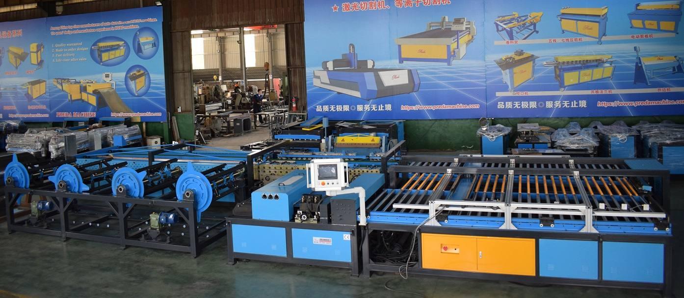
The programmed sequence handles repeatable preparation, but it does not remove the operator's role. The setter reads the drawing, enters or recalls the section program, confirms the first blank against the dimensions, and watches the run for size, notch or profile mismatch. First-blank checks after every size or gauge change are the main human gate in the flow; catching an off blank there prevents a reworked batch. Existing shop knowledge of seams and gauges still matters because it lets the setter recognize a bad panel before it leaves the station.
The line also does not replace downstream expertise. The blank it feeds still has its Pittsburgh edge rolled on a lockformer, its flange formed on a flange former, and its seam closed on a seam locker. A well-prepared blank reaches those stations in better condition, but seam tightness and flange flatness still depend on those machines' setup and roller condition. Treating the preparation line as if it completed the whole section usually moves quality problems downstream rather than removing them.
Common Station-Level Problems and Their Source
- Curled or uneven blank: usually leveling set for a different gauge; adjust before the shear cuts a stack of off blanks.
- Off-position bead or groove: profile setup from the previous section; re-measure on the first panel after a profile change.
- Poor box-corner closure: notch pattern or depth mismatch; check against the drawing before folding the batch.
- Blank out of square: feed wander or off-centre coil alignment; the shear cannot square a panel fed out of line.
- Edge dings between line and bench: cross-shop carry to a downstream station; align the exit side to the next bench.
Assign one first-blank check per station in the setup sheet
List the feed alignment, flatness, profile, notch and dimension checks on the line's setup sheet in station order. When a size changes, the setter runs those checks in sequence on the first blank rather than inspecting the finished folded box alone. Problems found this way trace back to the station that caused them instead of to the downstream locker.
Preda Care Service Promise
Every Preda Machine ships CE certified with a two-year warranty, backed by 24/7 technical support, free spare parts shipping, remote PLC programming assistance and a global agent network. A support engineer can review your section widths, gauge mix and weekly volume against the AML-3 and AML-6 configurations, and walk through the station setup and first-blank checks.
Plan the Preparation Line for Your Section Mix
Share the rectangular widths, gauges and weekly sections you produce, and we will map them to the AML-3 or AML-6 line configuration, including the station setup and first-blank check routine that keeps repeatable blank quality.
Compare Auto Duct Lines →Frequently Asked Questions
What stations make up an automatic duct line?
The preparation sequence runs from the coil car and feed through leveling, beading or grooving, notching and shearing to the panel exit. Lockforming, flanging and seam closing remain downstream stations; the line prepares and feeds the blank.
What thickness and width do the AML-3 and AML-6 cover?
Both process 0.45-1.5 mm material in 1300, 1500 and 1600 mm width configurations. The AML-3 runs at 12 m/min on a PLC Mitsubishi touchscreen, and the AML-6 at 16 m/min under computer control; both use a two-station coil car.
Does the line close the seam on the finished duct?
No. The line produces the prepared blank; the Pittsburgh seam and flange are formed and closed on downstream lockformer, flange former and seam locker stations. The line improves blank consistency for those stations rather than completing the section.
Which checks does the operator still perform?
The setter confirms coil alignment, flatness, profile position, notch pattern and final dimensions on the first blank after a size or gauge change, then monitors the run. First-blank checks keep station-level issues from reaching folded sections.